D SEAL TUBE FITTINGS: A VERSATILE FITTING FOR MANY APPLICATIONS
|
|||||||||||||||||||||||||||||||||||||||||||||||||||||||||||||||||||||||||||||||||||||||||||||||||||||||||||||||||||||||||||||||||||||||||||||||||||||||||||||||||||||||||||||||||||||||||||||||||||||||||||||||||||||||||||||||||||||||||||||||||||||||||||||||||||||||||||||||||||||||||||||||||||||||||||||||||||||||||||||||||||||||||||||||||||||||||||||||||||||||||||||||||||||||||||||||||||||||||||||||||||||||||||||||||||||||||||||||||||||||||||||||||||||||||||||||||||||||||||||||||||||||||||||||||||||||||||||||||||||||||||||||||||||||||||||||||||||||||||||||||||||||||||||||||||||||||||||||||||||||||||||||||||||||||||||||||||||||||||||||||||||||||||||||||||||||||||||||||||||||||||||||||||||||||||||||||||||||||||||||||||||||||||||||||||||||||||||||||||||||||||||||||||||||||||||||||||||||||||||||||||||||||||||||||||||||||||||||||||||||||||||||||||||||||||||||||||||||||||||||||||||||||||||||||||||||||||||||||||||||||||||||||||||||||||||||||||||||||||||||||||||||||||||||||||||||||||||||||||||||
|
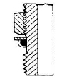
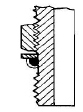
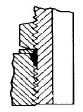
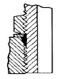
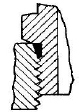
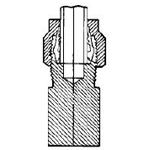
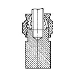
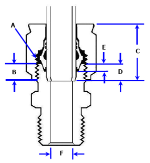
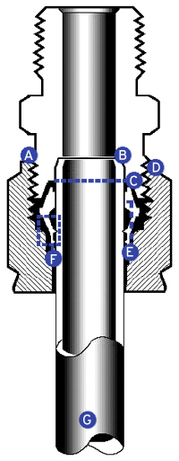
A. Fitting is tight when threads are out of sight. No tube marking or disassembly needed to assure proper make-up. B. Guide for the tube. Improves assembling time while reducing torque in order to obtain tight sealing. C. Safety margin. Guarantee a perfect sealing, even without exact placement of tubing in the fitting. Even if tube is not square cut it will hold firmly. D. D-Seal design prevents "locked-in" nut because body threads are not deformed outwardly. Always easy to disassemble when necessary. Stainless steel nuts are silver plted to reduce torque assemblies. E. Positive tubing support on both sides of gripping teeth absorbs shock, vibration and tube movement. Seal maintatined even under abusive or vibrating service. F. One-piece, collared sleeve. Controlled "bite" does not deform tubing and constrict flow, yes D-Seal holds to burst pressures of tubing. "Reserve gripping power" of second gripping tooth provides fresh seal on every remake. Positive seal maintained, even after repeated disassembly, without tubing construction. G. D-Seal tube fittings can be used on varying wall thickness tubing without altering performance results. |
||||||||||||||||||||||||||||||||||||||||||||||||||||||||||||||||||||||||||||||||||||||||||||||||||||||||||||||||||||||||||||||||||||||||||||||||||||||||||||||||||||||||||||||||||||||||||||||||||||||||||||||||||||||||||||||||||||||||||||||||||||||||||||||||||||||||||||||||||||||||||||||||||||||||||||||||||||||||||||||||||||||||||||||||||||||||||||||||||||||||||||||||||||||||||||||||||||||||||||||||||||||||||||||||||||||||||||||||||||||||||||||||||||||||||||||||||||||||||||||||||||||||||||||||||||||||||||||||||||||||||||||||||||||||||||||||||||||||||||||||||||||||||||||||||||||||||||||||||||||||||||||||||||||||||||||||||||||||||||||||||||||||||||||||||||||||||||||||||||||||||||||||||||||||||||||||||||||||||||||||||||||||||||||||||||||||||||||||||||||||||||||||||||||||||||||||||||||||||||||||||||||||||||||||||||||||||||||||||||||||||||||||||||||||||||||||||||||||||||||||||||||||||||||||||||||||||||||||||||||||||||||||||||||||||||||||||||||||||||||||||||||||||||||||||||||||||||||||||||||
|
By examining features and characteristics of D-Seal tube fittings, you will quickly discover why they are ideal fitting for standard and critical applications in instrumentation, chemical and petrochemical industries, refineries, pneumatic and hydraulic equipment, and other fluid transmission operations.
Compact design saves space. A butt-joint type design and freeding from flaring premit bends to be made exceptionally close to the tube end. In areas where Space is limited, tubing must extend through the sleeve but exct placement of tubing in the futting is not critical. Available in a variety of metals, styles and sizes. D-Seal variety allows you to specify one product to complete the entire job. Choose from brass, steel and 316 stainless steel. Meets low and high pressure applications. D-Seal tube fittings are recommended for low or high pressure service, within the safe pressure ranges of the most commonly used types of commercially available tubing. Performance in vaccum applications. Independent lab tests of D-Seal tube fittings indicate no leakage when tested by means of a mass spectrometeer leak detector, adjusted to indicate a leakage rate of 1.0 x 10⁻¹⁰ standard cubit centimeters of helium per second. Designed for high temperatures. D-Seal tube fittings meet the following temperature limitations for tubing systems: 800°F/426°C with stainless steel 425°F/218°C with copper and brass 600°F/315°C with steel Exceed vibration and shock standards. D-Seal tube fittings exceed the minimum requirement of 10,000,000 cycles of vibration required under SAE AS18280 (reference). D-Seal allow a overhand deflection, since the sleeve gives positive tubing support on both sides of the sealing with tube. The pivot point which causes leakage in many fittings is eliminated in D-Seal fittings. Repeated assembly. SAE AS18280 (reference) also requires that a fitting connection be taken apart and remade a minimum of eight times. Our engineering standards specify a minimum of sixteen assemblies and disassemblies. The reserve gripping action of D-Seal fittings permits the fitting to exceed this minimum, while still remaining free from leakage. Exceed others requirements. D-Seal tube fittings also exceed the following requirements under SAE AS 18280 (reference): 3.6.1 Proof Pressure; 3.6.2 Burst Pressure; 3.6.3 Pneumatic Pressure; 3.6.4 Repeated Assembly; 3.6.5 Impulse; 3.6.6 Flexure; 3.6.7 Joint Strength.  MATERIALS FOR STANDARD D-SEAL TUBE FITTINGS MATERIALS FOR STANDARD D-SEAL TUBE FITTINGS
D-Seal tube fittings are available as standard in stainless steel, steel and brass. Straight fittings are machined from cold finished bar stock and shaped bodies from forgings. Brass fittings • Elbows, tees, and crosses: Brass forgings ASTM B124 UNS-C37700. • Connectors, unions, sleeves and nuts: stress relieved brass bar stock ASTM B16 UNS-C36000. Steel fittings • Elbows and tees: forged low carbon steel ASTM A576-12L14. • Connectors, unions and nuts: low carbon steel bar stock ASTM A576-12L14. • Sleeves: steel bar stock ASTM A108 UNS-G114400, stress relieved, black phosphate finish. • Bodies and nuts are furnished with yellow zinc plate finish as standard. Stainless steel fittings • Elbows and tees: stainless steel forging ASTM A182 UNS-S31600. • Connectors and unions: stainless steel bar stock, ASTM A276 UNS-S31600. • Nuts: stainless steel bar stock, ASTM A276 UNS-S31600 silver plated to provide reduced torque assemblies. • Sleeves: stainless steel bar stock, ASTM A276 UNS-S31600 or ASTM A564 UNS-S17400/630 H1150 (17-4PH). MAXIMUM WORKING PRESSURES (FRACTIONAL TUBING) Fitting material: Type 316 bodies and nuts with 316 sleeves or 17-4PH. Tubing material: Type 304 or 316 annealed stainless steel.
1. Working pressure based on room temperature (72°F/22°C) service. For elevated temperature service, multiply these pressures by derating factors obtained from the chart here. 2. Fittings with tapered pipe threads (NPT or NPTF) may have pressure capabilities limited to that of the pipe threads. Such fittings should not be used at pressures exceeding those listed here. Fitting material: Steel Tubing material: Steel, SAE 1010, Dead Soft low carbon, cold draw*.
Note: 1. Working pressure based on room temperature (72°F/22°C) service. For elevated temperature service, multiply these pressures by derating factors obtained from the chart here. 2. Fittings with tapered pipe threads (NPT or NPTF) may have pressure capabilities limited to that of the pipe threads. Such fittings should not be used at pressures exceeding those listed here. Fitting material: Brass Tubing material: Copper, Dead Soft, Seamless
1. Working pressure based on room temperature (72°F/22°C) service. For elevated temperature service, multiply these pressures by derating factors obtained from the chart here. 2. Fittings with tapered pipe threads (NPT or NPTF) may have pressure capabilities limited to that of the pipe threads. Such fittings should not be used at pressures exceeding those listed here. Fitting material: Brass Tubing material: Copper, Half Hard, Seamless
1. Working pressure based on room temperature (72°F/22°C) service. For elevated temperature service, multiply these pressures by derating factors obtained from the chart here. 2. Fittings with tapered pipe threads (NPT or NPTF) may have pressure capabilities limited to that of the pipe threads. Such fittings should not be used at pressures exceeding those listed here. MAXIMUM WORKING PRESSURES (METRIC TUBING) Fitting material: Steel Tubing material: Steel, SAE 1010, Dead Soft low carbon, DIN 2391.
1. Working pressure based on room temperature (72°F/22°C) service. For elevated temperature service, multiply these pressures by derating factors obtained from the chart here. 2. Fittings with tapered pipe threads (NPT or NPTF) may have pressure capabilities limited to that of the pipe threads. Such fittings should not be used at pressures exceeding those listed here. Fitting material: Type 316 bodies and nuts with 316 sleeves or 17-4PH. Tubing material: Type 304 or 316 annealed stainless steel.
1. Working pressure based on room temperature (72°F/22°C) service. For elevated temperature service, multiply these pressures by derating factors obtained from the chart here. 2. Fittings with tapered pipe threads (NPT or NPTF) may have pressure capabilities limited to that of the pipe threads. Such fittings should not be used at pressures exceeding those listed here. Fitting material: Brass Tubing material: Copper,Dead Soft, Seamless
1. Working pressure based on room temperature (72°F/22°C) service. For elevated temperature service, multiply these pressures by derating factors obtained from the chart here. 2. Fittings with tapered pipe threads (NPT or NPTF) may have pressure capabilities limited to that of the pipe threads. Such fittings should not be used at pressures exceeding those listed here. Fitting material: Brass Tubing material: Copper,Half Hard, Seamless
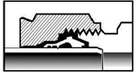
1. Working pressure based on room temperature (72°F/22°C) service. For elevated temperature service, multiply these pressures by derating factors obtained from the chart here. 2. Fittings with tapered pipe threads (NPT or NPTF) may have pressure capabilities limited to that of the pipe threads. Such fittings should not be used at pressures exceeding those listed here. PORT SEALING METHODS 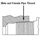 Standard pipe threads are the common connections used for tube fittings, valves and other components. Brass and carbon steel fittings are furnished with long DRYSEAL pipe threads (dry sealing) DRYSEAL threads have a flat on the root wider than the flat on the crest. This generates and increased deformation in the threads, increasing the sealing effect where it is necessary, since leakages, in these types of threads, are caused by a clearance between the root and crest. Standard pipe threads are the common connections used for tube fittings, valves and other components. Brass and carbon steel fittings are furnished with long DRYSEAL pipe threads (dry sealing) DRYSEAL threads have a flat on the root wider than the flat on the crest. This generates and increased deformation in the threads, increasing the sealing effect where it is necessary, since leakages, in these types of threads, are caused by a clearance between the root and crest.
The additional length of DRYSEAL pipe threads allows further reassemblies and, in combination with the thread form, provides a tighter joint. 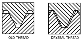 When NPTF is specified (brass and steel fittings), port end dimensions will be furnished in accordance to SAE J476a. When NPT is specified (stainless steel fittings), port end dimensions will be furnished in accordance to ASME B1.20.1. ISO Parallel and Tapered Pipe Thread The ISO 228/1 and 7/1 threads were created by the International Standards Organization (ISO) to standardize the nomenclature of several interenational pipe threads. ISO 228/1 is a parallel thread and ISO 7/1 is a tapered thread. 228/1 With 228/1 parallel threads, the seal is usually made by metal-to-metal contact against the female port or with a gasket.
7/1 The 7/1 is a tapered thread system where a pressure tight seal is made on the thread. The 7/1 looks similar to the NPT thread, except the 7/1 has a 55° included angle on the thread. Also the number of threads per inch varies slightly.
PIPE THREAD SEALANT A thread sealant should always be used when assembling tapered threads easily found in the market such as Teflon® tape. How to apply 1. 1/4 in. wide tape should be used on 1/8, 1//4, and 3/8 in. male tapered pipe threads. 1/2 in. wide tape should be used on 1/2 in. and larger tapered pipe threads. Tape should be used only on male tapered pipe threads. Do not use on flared, coned, or tube fittings ends. 2. Thoroughly clean male and female threads, assuring the removal of all previously applied antiseize compound or tape. 3. Wrap tape in the direction of thread spiral of male pipe thread beginning with first thread. Tape should never extend beyond or overhang the first thread as tape could shredand get into fluid system. 4. Using care not to contaminate the tape, encircle the threads and join together with a very slight overlap. Wrap to the top of threads. (A double wrap is suggested on stainless steel pipe threads). Draw free end around threads tautly so that it conforms to the thread surface. Allow for a slight overlap and cut or tear off tape. Press in firmly at overlap point. Tape will hold in position by itself. If tape does not lie flat, press into the threads with thumb nail. STRAIGHT THREAD O-RING SEAL 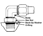 For conntecting into ports of hydraulic valves and others parts, the O-Ring seal offers the following advantages: For conntecting into ports of hydraulic valves and others parts, the O-Ring seal offers the following advantages:
• It eliminates the possibility of broken fittings, deformed housing, and cracking of ports which can result from over-torquing with pipe threads. • An O-Ring seal also lets you position elbows and tees so that tube ends will always be in proper alignment. D-SEAL elbows with straight thread O-Ring seal have a backup washer crimped into position in the O-Ring groove ahead of the lock nut. This washer prevents the O-Ring from extruding into threads when the joint is under pressure. Steel fittings are furnished with Buna-N O-Ring and stainless steel fittings with Viton O-Ring. When specifying O-Rings, they must be of a compound compatible with the fluid in the system. Assembly instructions for adjustable fittings
GAS SERVICE Some gases (air, hydrogen, helium, nitrogen, etc.) due to their small molecule dimensions may leak easily. Some surface defects on the tubing can provide these leaks. The most successful connection for gas service will occur if all installation instructions are carefully followed and the heavier wall thickness of tubing are selected. A heavy wall tube resists sleeve action more than a thin wall tube, allowing the sleeves to overcome minor surface imperfections. A thin wall tube may collapse, thus offering little resistance to sleeve action during pull-up. For gas services, use a wall thickness no less than those shown.
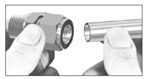
D-SEAL ASSEMBLY INSTRUCTIONS D-Seal tube fittings are provided fully assembled, (body, nut and sleeve), ready for immediate use. Disassembly before use is not recommended and can result in dirt or foreign material getting into fitting and causing leaks. 1. For best restuls A. Always use a fitting whose materials are compatible with the tubing that is used. (e.g. when using stainless steel tubing, use 316 stainless steel fittings). This will minimize the possibility of chemical or galvanic corrosion. B. Keep in mind that the sleeve should always have a hardness at least equal to that of the tubing used. Type 316 sleeves may be used with seamless annealed stainless steel tubing. C. When assembling fittings to both ends of a length of tubing, partly tighten the nut at one end until the tube cannot be turned by hand, then fully tighten the fitting at the other end until the threads are completely covered. Finally, finish tightening the first end until those threads are completely covered. 2. Preperation of tubing A. Cut tubing with a tube cutter or a hacksaw with a fine tooth blade and a sawing vise. B. Deburr inside and outside of tubing sufficiently to remove burrs to assure that sleeve will slip freely onto the tube. 3. Assembly
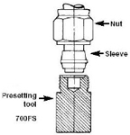
4. Remake(s) You may disassemble and reassemble D-Seal tube fittings many times. When a D-SEAL connection is to be reassembled, retighten the nut 1/6 turn (one hex flat) beyond the previously assembled position. This will properly reseat the connections. PRESETTING INSTRUCTIONS Normally it is not necessary to preset D-SEAL tube fittings. Presetting is ordinarily used only where adequate torque cannot be applied at a point of installation due to space restrictions, or for pre-production assembly. For these cases, sepcial presetting tools are available. In an emergency, a fitting body may be used as a presetting tool. 1. Preperation of tubing A. Cut tubing with a tube cutter or a hacksaw with a fine tooth blade and a sawing vise. B. Deburr inside and outside of tubing sufficiently to remove burrs to assure that sleeve will slip freely onto tube. 2. Presetting
FITTING PLUG Installation Instructions
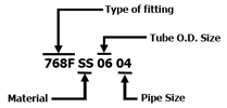
ORDERING INFORMATION The part numbering system for D-Seal tube fittings is designed so that you can easily identify the type, configuration, size and material of the fitting as well as an applicable tubing size and thread connection. The part number describes completely assembled fittings. 1. Types of fitting Inch - The catalog number indicates a fitting for inch size tubing. Example: 768F - Male connector for inch tubing. Meteric - An "M" included before the part number indicates a fitting for metric size tubing. Example: M768F - Male connector for metric tubing. S - Steel SS - 316 Stainless steel PH - Stainless steel ASTM A564 UNS 17400 (17-4PH). Only the sleeves are supplied in this material. B - Brass BO - To order D-Seal fittings bodies only, add suffix "BO" to part number. Example: 768 SS BO 0808. 2. Port end threads NPTF pipe threads are standard for all port ends on D-Seal fittings, except for stainless steel fittings which are NPT. Other types of port end threads can be supplied under request. 3. How to specify port end threads NPT/NPTF - No suffix required. * BSPT - (ISO 7/1) - Add suffix RK after size designator. Example: M768FSS1004RK * BSPP - (ISO 2281 - DIN3852-2 Form A) - Add suffix RZ after size designator. Example: M768FSS1004RZ * Under request to Detroit. 4. Other examples
D-SEAL PRESETTING TOOL Made of hardened stainless steel. For presetting D-Seal fittings. Presetting is ordinarily used only when adequate torque cannot be applied at point of installation due to space restrictions, or for pre-production assembly. Maintenance of presetting tool Handle presetting tools with care, being sure that the threads and 12° seat are not nicked or in any way damaged. Do not attempt to rework took if it becomes damaged - obtain a new tool. Keep tools stored so that they will not be damaged. "Seal-peel" dip or a similar protective coating that is used for gauges and tools is recommended.
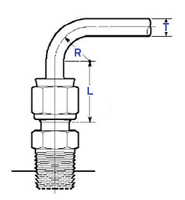
BENDED TUBING When installing fittings near tube bends, there must be a sufficient straight length of tubing to allow the tube to be bottomed in the tube fitting. See chart below.
IDENTIFYING OF METRIC D-SEAL TUBE FITTINGS FROM FACTIONAL All metric tube fittings have a knurled shoulder on the nut and sleeve. 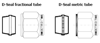
D-SEAL (DETROIT) X HI-SEAL (IMPERIAL EASTMAN) 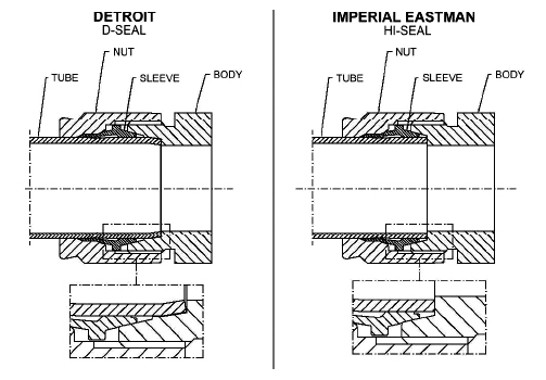 Detroit's D-Seal tube fitting presents the "Guide for the tube," which is a seat extension. This new design presents the following advantages comparing to Imperial's Hi-Seal tube fittings:
However it is not possible to use tubes gripped by Detroit's sleeve with Imperial's body due to the Detroit's D-Seal body needs a larger tube length. The higher quality of the components has permitted the use of D-Seal in the most different applications such as instrumentation, control and process systems in chemical, petrochemical, oil and gas, paper and cellulose, and siderurgy industries, among others. DIMENSIONS Dimensions, in inches and millimeters, are for reference only and are subject to change. Dimensions are shows with nuts finger-tight. SAFETY PRECAUTIONS
DIMENSIONAL DATA
Important notes: 1. When metric and inch tube O.D. are shown in the same line, the same body is used for both applying nut and sleeve for specific use. 2. When metric and inch tube O.D. are shown in different lines, bodies are different in each case.
| |||||||||||||||||||||||||||||||||||||||||||||||||||||||||||||||||||||||||||||||||||||||||||||||||||||||||||||||||||||||||||||||||||||||||||||||||||||||||||||||||||||||||||||||||||||||||||||||||||||||||||||||||||||||||||||||||||||||||||||||||||||||||||||||||||||||||||||||||||||||||||||||||||||||||||||||||||||||||||||||||||||||||||||||||||||||||||||||||||||||||||||||||||||||||||||||||||||||||||||||||||||||||||||||||||||||||||||||||||||||||||||||||||||||||||||||||||||||||||||||||||||||||||||||||||||||||||||||||||||||||||||||||||||||||||||||||||||||||||||||||||||||||||||||||||||||||||||||||||||||||||||||||||||||||||||||||||||||||||||||||||||||||||||||||||||||||||||||||||||||||||||||||||||||||||||||||||||||||||||||||||||||||||||||||||||||||||||||||||||||||||||||||||||||||||||||||||||||||||||||||||||||||||||||||||||||||||||||||||||||||||||||||||||||||||||||||||||||||||||||||||||||||||||||||||||||||||||||||||||||||||||||||||||||||||||||||||||||||||||||||||||||||||||||||||||||||||||||||||||||